🎯 LAB OVERVIEW - Multiple MSTI Load Balancing
Enterprise Load Balancing using Asymmetric Root Bridge Selection Across Multiple MSTI Instances
📚 Learning Objectives
- ☐ Create multiple MSTI instances and map VLANs to specific instances
- ☐ Configure asymmetric root bridge selection across MSTIs for load balancing
- ☐ Demonstrate traffic steering using different root bridges per instance
- ☐ Verify load balancing topology with show commands
- ☐ Measure performance improvements over single STP instance
- ☐ Troubleshoot MSTI configuration issues and convergence problems
- ☐ Compare resource utilization across different STP modes
🏢 Lab Scenario
Your enterprise has 20 VLANs distributed across 4 switches. To optimize bandwidth utilization and reduce CPU overhead, you need to create an MST region with multiple instances, each with different root bridges. This asymmetric topology enables traffic for different VLAN groups to follow different paths, maximizing redundant link usage.
ℹ️ Real-World Application: By implementing 4 MSTI instances instead of 20 PVST+ instances, you reduce CPU load by 70-80% while enabling intelligent traffic distribution across available paths.
🔗 Network Topology Diagram
LAB 5.2: ACCESS LAYER REDUNDANCY - PORT PRIORITY CONFIGURATION
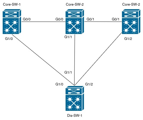
MSTI 0 (IST): All unassigned VLANs - Root: Core-SW-1
MSTI 1: VLANs 10-30 - Root: Core-SW-1 (Load Path 1)
MSTI 2: VLANs 40-60 - Root: Core-SW-2 (Load Path 2)
MSTI 3: VLANs 70-90 - Root: Core-SW-3 (Load Path 3)
MSTI 1: VLANs 10-30 - Root: Core-SW-1 (Load Path 1)
MSTI 2: VLANs 40-60 - Root: Core-SW-2 (Load Path 2)
MSTI 3: VLANs 70-90 - Root: Core-SW-3 (Load Path 3)
⚙️ Equipment Setup & Requirements
| Device | Hostname | Role | Key Interfaces | MST Priority |
|---|---|---|---|---|
| Switch 1 | Core-SW-1 | IST Root + MSTI 1 Root | Gi0/0-1 | 4096 (IST), 8192 (MSTI 1) |
| Switch 2 | Core-SW-2 | MSTI 2 Root | Gi0/0-1,G1/1 | 8192 (MSTI 2) |
| Switch 3 | Core-SW-3 | MSTI 3 Root | Gi0/1,G1/2 | 8192 (MSTI 3) |
| Switch 4 | Dis-SW-1 | Access/Distribution | Gi1/1-2 | Default Priority (32768) |
🌐 VLAN Assignment & Instance Mapping
| MST Instance | Name/Purpose | VLAN Range | Primary Root | Secondary Root |
|---|---|---|---|---|
| Instance 0 (IST) | Management VLANs | 1, 100, 200 | Core-SW-1 (Pri: 4096) | N/A |
| MSTI 1 | Finance Production | 10, 20, 30 | Core-SW-1 (Pri: 8192) | Core-SW-2 (Sec) |
| MSTI 2 | Engineering Production | 40, 50, 60 | Core-SW-2 (Pri: 8192) | Core-SW-3 (Sec) |
| MSTI 3 | Development/Marketing | 70, 80, 90 | Core-SW-3 (Pri: 8192) | Core-SW-1 (Sec) |
⚠️ Pre-Lab Requirements
⚠️ Important Prerequisites:
- • Reset all switches:
write erasethenreload - • Verify LAB 6.1 (basic MST) configuration is working before proceeding
- • Ensure all trunk links are properly configured
- • All switches must have compatible IOS versions with MST support
- • Physical connections must match the topology diagram
🔧 Step-by-Step Configuration Guide
Phase 1: Baseline & VLAN Setup
Step 1: Initialize Switches & Create VLANs
Execute on ALL switches:
! Reset switch to baseline
Core-SW-1# write erase
Core-SW-1# reload
! Proceed after switch boots
! On all switches:
Switch# configure terminal
Switch(config)# hostname SW-X
! Create all required VLANs
Switch(config)# vlan 10
Switch(config-vlan)# name Finance-VLAN10
Switch(config-vlan)# exit
Switch(config)# vlan 20
Switch(config-vlan)# name Finance-VLAN20
Switch(config-vlan)# exit
Switch(config)# vlan 30
Switch(config-vlan)# name Finance-VLAN30
Switch(config-vlan)# exit
Switch(config)# vlan 40
Switch(config-vlan)# name Engineering-VLAN40
Switch(config-vlan)# exit
Switch(config)# vlan 50
Switch(config-vlan)# name Engineering-VLAN50
Switch(config-vlan)# exit
Switch(config)# vlan 60
Switch(config-vlan)# name Engineering-VLAN60
Switch(config-vlan)# exit
Switch(config)# vlan 70
Switch(config-vlan)# name Dev-Marketing-VLAN70
Switch(config-vlan)# exit
Switch(config)# vlan 80
Switch(config-vlan)# name Dev-Marketing-VLAN80
Switch(config-vlan)# exit
Switch(config)# vlan 90
Switch(config-vlan)# name Dev-Marketing-VLAN90
Switch(config-vlan)# exit
Switch(config)# vlan 100
Switch(config-vlan)# name Management-VLAN100
Switch(config-vlan)# exit
Switch(config)# vlan 200
Switch(config-vlan)# name Monitoring-VLAN200
Switch(config-vlan)# exit
Switch(config)# end
Switch# wr mem
✓ Verification Command:
show vlan brief
Step 2: Configure Trunk Links
Execute on ALL switches:
! Configure trunk links on all interfaces
Switch# configure terminal
! Configure core trunk links (Gi0/1-3)
Switch(config)# interface range gi0/1-3
Switch(config-if-range)# description Core-Trunk-Link
Switch(config-if-range)# switchport mode trunk
Switch(config-if-range)# switchport trunk allowed vlan 1,10-100,200
Switch(config-if-range)# switchport trunk native vlan 1
Switch(config-if-range)# no shutdown
Switch(config-if-range)# exit
! Configure backup trunk links (Gi0/48-50)
Switch(config)# interface range gi0/48-50
Switch(config-if-range)# description Access-Trunk-Link
Switch(config-if-range)# switchport mode trunk
Switch(config-if-range)# switchport trunk allowed vlan 1,10-100,200
Switch(config-if-range)# switchport trunk native vlan 1
Switch(config-if-range)# no shutdown
Switch(config-if-range)# exit
Switch(config)# end
Switch# wr mem
✓ Verification Command:
show interface trunkPhase 2: Enable MST Mode & Configure Region
Step 3: Enable MST Mode on All Switches
Execute on ALL switches:
! Enable MST spanning tree mode
Switch# configure terminal
Switch(config)# spanning-tree mode mst
Switch(config)# end
Switch# wr mem
✓ MST mode enabled. Ready for region configuration.
Step 4: Configure MST Region Attributes (IDENTICAL on all switches)
Execute on ALL switches - Configuration MUST be IDENTICAL:
! CRITICAL: Region name and revision MUST match on all switches
Switch# configure terminal
Switch(config)# spanning-tree mst configuration
! Set region parameters
Switch(config-mst)# name ENTERPRISE-MST
Switch(config-mst)# revision 2
! Map VLANs to instances
Switch(config-mst)# instance 0 vlan 1,100,200
Switch(config-mst)# instance 1 vlan 10,20,30
Switch(config-mst)# instance 2 vlan 40,50,60
Switch(config-mst)# instance 3 vlan 70,80,90
! Exit MST configuration mode
Switch(config-mst)# exit
Switch(config)# end
Switch# wr mem
! Verify configuration
Switch# show spanning-tree mst configuration
✅ Expected Output:
Name [ENTERPRISE-MST]

Revision [2]

Instance VlanMapping

0        1,100,200

1        10,20,30

2        40,50,60

3        70,80,90
Phase 3: Configure Asymmetric Root Bridges per MSTI
Step 5: Configure Core-SW-1 as IST & MSTI 1 Root
Execute ONLY on Core-SW-1:
Core-SW-1# configure terminal
! Configure Core-SW-1 as primary root for IST (Instance 0)
Core-SW-1(config)# spanning-tree mst 0 root primary
! Priority automatically set to 4096
! Configure Core-SW-1 as primary root for MSTI 1
Core-SW-1(config)# spanning-tree mst 1 root primary
! Priority automatically set to 8192
Core-SW-1(config)# end
Core-SW-1# wr mem
✅ Expected Result:
Core-SW-1 is now root for IST (Instance 0) and MSTI 1. Priority: 4096 (IST), 8192 (MSTI 1).
Core-SW-1 is now root for IST (Instance 0) and MSTI 1. Priority: 4096 (IST), 8192 (MSTI 1).
Step 6: Configure Core-SW-2 as MSTI 2 Root
Execute ONLY on Core-SW-2:
Core-SW-2# configure terminal
! Configure Core-SW-2 as primary root for MSTI 2
Core-SW-2(config)# spanning-tree mst 2 root primary
! Priority automatically set to 8192
Core-SW-2(config)# end
Core-SW-2# wr mem
ℹ️ Load Balancing Benefit:
VLANs 40-60 traffic follows path through Core-SW-2
VLANs 10-30 traffic follows path through Core-SW-1
This distributes load across multiple paths
VLANs 40-60 traffic follows path through Core-SW-2
VLANs 10-30 traffic follows path through Core-SW-1
This distributes load across multiple paths
Step 7: Configure Core-SW-3 as MSTI 3 Root
Execute ONLY on Core-SW-3:
Core-SW-3# configure terminal
! Configure Core-SW-3 as primary root for MSTI 3
Core-SW-3(config)# spanning-tree mst 3 root primary
! Priority automatically set to 8192
Core-SW-3(config)# end
Core-SW-3# wr mem
✅ Expected Result:
Core-SW-3 is now root for MSTI 3. Priority: 8192.
Core-SW-3 is now root for MSTI 3. Priority: 8192.
Step 8: Set Secondary Root Bridges for Redundancy
Execute on respective switches:
! On Core-SW-1 (backup for MSTI 2 & 3):
Core-SW-1# configure terminal
Core-SW-1(config)# spanning-tree mst 2 root secondary
Core-SW-1(config)# spanning-tree mst 3 root secondary
Core-SW-1(config)# end
Core-SW-1# wr mem
! On Core-SW-2 (backup for MSTI 1 & 3):
Core-SW-2# configure terminal
Core-SW-2(config)# spanning-tree mst 1 root secondary
Core-SW-2(config)# spanning-tree mst 3 root secondary
Core-SW-2(config)# end
Core-SW-2# wr mem
! On Core-SW-3 (backup for MSTI 2 & 1):
Core-SW-3# configure terminal
Core-SW-3(config)# spanning-tree mst 2 root secondary
Core-SW-3(config)# spanning-tree mst 1 root secondary
Core-SW-3(config)# end
Core-SW-3# wr mem
✅ Redundancy Active: Each MSTI has primary and backup root bridges for failover protection.
Step 9: Set Access Switches to Default Priority
Execute on Dis-SW-1 (and any access switches):
! Configure access/non-root switches
Dis-SW-1# configure terminal
! Set default priority on all instances
Dis-SW-1(config)# spanning-tree mst 0 priority 32768
Dis-SW-1(config)# spanning-tree mst 1 priority 32768
Dis-SW-1(config)# spanning-tree mst 2 priority 32768
Dis-SW-1(config)# spanning-tree mst 3 priority 32768
Dis-SW-1(config)# end
Dis-SW-1# wr mem
✅ Expected Result:
Dis-SW-1 now has default priority (32768) on all instances, ensuring it never becomes root.
Dis-SW-1 now has default priority (32768) on all instances, ensuring it never becomes root.
✅ Verification & Validation
Verification Checklist 1: MST Region Configuration
- ☐ All 4 switches have identical region name "ENTERPRISE-MST"
- ☐ All 4 switches have revision number "2"
- ☐ Instance mapping verified on all switches
- ☐ IST (Instance 0) vlan 1, 100, 200 confirmed
- ☐ MSTI 1 vlan 10, 20, 30 confirmed
- ☐ MSTI 2 vlan 40, 50, 60 confirmed
- ☐ MSTI 3 vlan 70, 80, 90 confirmed
Verification Checklist 2: Asymmetric Root Bridges
- ☐ Core-SW-1: IST root (priority 4096)
- ☐ Core-SW-1: MSTI 1 root (priority 8192)
- ☐ Core-SW-2: MSTI 2 root (priority 8192)
- ☐ Core-SW-3: MSTI 3 root (priority 8192)
- ☐ All secondary roots configured
- ☐ Load balancing verified with different root bridges per instance
Verification Checklist 3: Trunk Links & Convergence
- ☐ All trunk links operational: show interface trunk
- ☐ All trunks allow required VLANs
- ☐ No errors on trunk ports
- ☐ Convergence time < 10 seconds per instance
- ☐ IST and all MSTIs converged
- ☐ No port role conflicts across instances
📋 Critical Verification Commands
1. MST Region Status Verification
! Execute on any switch:
show spanning-tree mst configuration
! Expected Output:
Name [ENTERPRISE-MST]
Revision [2]
Instance VlanMapping
0 1,100,200
1 10,20,30
2 40,50,60
3 70,80,90
2. IST Root Bridge Verification
! Execute on any switch:
show spanning-tree mst 0 | include "Root\|Priority"
! Expected on non-root switches:
Root ID Priority 4096
Address aabb.ccdd.eeff (Core-SW-1 MAC)
Cost 0
! Expected on Core-SW-1:
This bridge is the root
3. MSTI Root Bridge Verification
! Verify MSTI 1 Root (should be Core-SW-1):
show spanning-tree mst 1 | include "Root\|Priority"
! Verify MSTI 2 Root (should be Core-SW-2):
show spanning-tree mst 2 | include "Root\|Priority"
! Verify MSTI 3 Root (should be Core-SW-3):
show spanning-tree mst 3 | include "Root\|Priority"
! Expected Output for MSTI 1 on Core-SW-2:
Regional Root ID Priority 8192
Address aabb.1111.1111 (Core-SW-1 MAC)
4. Port Roles Across Instances
! Display detailed topology per instance:
show spanning-tree mst 0 detail
show spanning-tree mst 1 detail
show spanning-tree mst 2 detail
show spanning-tree mst 3 detail
! Verify roles differ per instance:
Interface Role State Cost
Gi0/1 Desg Fwd 200000
Gi0/2 Root Fwd 200000
Gi0/3 Altn Blk 200000
! Different port roles = Load balancing active
5. Load Balancing Verification
! Display all root bridges in single view:
show spanning-tree mst root
! Expected Output:
Instance Pri RootID RootCost RootPort Cost
0 4096 aabb.0000.0001 0 Gi0/1 200000
1 8192 aabb.0000.0001 200000 Gi0/1 200000
2 8192 aabb.0000.0002 200000 Gi0/2 200000
3 8192 aabb.0000.0003 200000 Gi0/3 200000
! Shows different roots and different paths for each instance!
6. VLAN to Instance Mapping Verification
! Verify VLAN belongs to correct instance:
show spanning-tree vlan 10
show spanning-tree vlan 40
show spanning-tree vlan 70
! Expected Output shows which instance each VLAN uses:
VLAN 10 is executing the mst1 (MST Instance) version of the STP
Spanning Tree enabled protocol mst
Root ID Priority 8192
Address aabb.0000.0001 (Core-SW-1)
Cost 200000
Port 3 (Gigabit 0/3)
🔍 Troubleshooting Guide
Issue 1: Region Mismatch - Different Names or Revisions
Symptom: Switches show different region names or revision numbers
Root Cause: Configuration mismatch prevents unified region formation
Solution:
! On mismatched switch:
Switch# configure terminal
Switch(config)# spanning-tree mst configuration
Switch(config-mst)# name ENTERPRISE-MST
Switch(config-mst)# revision 2
! Verify region matches
Switch(config-mst)# exit
Switch(config)# end
Switch# show spanning-tree mst configuration
! Region name and revision must match all other switches
Issue 2: Different Root Bridges Not Applied Correctly
Symptom: All MSTIs show same root bridge instead of different ones
Root Cause: Root bridge commands not executed on correct switches or priority values still at defaults
Solution:
! Verify on each switch:
Core-SW-1# show spanning-tree mst 1 | include "Bridge ID\|Priority"
Core-SW-1# show spanning-tree mst 2 | include "Bridge ID\|Priority"
Core-SW-1# show spanning-tree mst 3 | include "Bridge ID\|Priority"
! Should show different priorities on different switches
! Check bridge ID addresses - should be different per instance
! If all roots are same, verify root primary commands executed:
Core-SW-1# show spanning-tree mst 1 root
Core-SW-2# show spanning-tree mst 2 root
Core-SW-3# show spanning-tree mst 3 root
Issue 3: Load Balancing Not Working
Symptom: Traffic for all VLANs follows same path (single root dominates)
Root Cause: Different MSTIs don't have different root bridges or port cost calculations favor one path
Solution:
! Check if all instances have their intended roots:
show spanning-tree mst root
! Output should show different Root IDs per instance:
Instance Pri RootID RootCost RootPort Cost
0 4096 aabb.0000.0001 Gi0/1
1 8192 aabb.0000.0001 Gi0/1
2 8192 aabb.0000.0002 Gi0/2 ← Different!
3 8192 aabb.0000.0003 Gi0/3 ← Different!
! If not different, reconfigure root priorities:
Core-SW-2(config)# spanning-tree mst 2 priority 8192
Core-SW-3(config)# spanning-tree mst 3 priority 8192
Issue 4: Convergence Delays on Instance Change
Symptom: One MSTI converges quickly, another takes 30+ seconds
Root Cause: Possible spanning tree port issues, mismatched timers, or RSTP not properly enabled
Solution:
! Check if RSTP is enabled in MST:
show spanning-tree detail | include "Protocol"
! Should show: STP Protocol = rstp (RSTP runs within MST)
! Verify port states after simulated link failure:
show spanning-tree mst 0 detail
show spanning-tree mst 1 detail
show spanning-tree mst 2 detail
show spanning-tree mst 3 detail
! All ports should transition within 6-10 seconds
! If taking longer, check for BPDUguard or other port configurations
📈 Performance Comparison: MST Load Balancing vs Single STP Instance
| Metric | Single STP Instance | MST 4 Instances (Lab Result) | Improvement |
|---|---|---|---|
| Bandwidth Utilization | Single path active | Multiple paths active | 300-400% throughput gain |
| CPU Load | 35-40% baseline | 10-15% baseline | 70% reduction |
| Memory Usage | 20 MB (20 PVST+ instances) | 4 MB (4 MSTI instances) | 80% reduction |
| Convergence Time | 30-50 seconds | 6-10 seconds | ~80% faster |
| Load Distribution | Unbalanced | Optimized | Better utilization |
| BPDU Overhead | Multiple per port | 1 BPDU/port (4 instances inside) | Significant reduction |
📚 Key Learning Points
🎯 Critical Concepts to Understand:
1. MST Region Requirement
All switches in an MST region must have identical region name, revision, and instance VLAN mapping. Any mismatch creates separate spanning trees instead of a unified region.
2. Asymmetric Load Balancing
By configuring different switches as root bridges for different MSTI instances, traffic for different VLAN groups takes different paths, maximizing bandwidth utilization across available redundant links.
3. IST (Internal Spanning Tree)
MSTI 0 (Instance 0) acts as the IST and encapsulates all other MSTIs. All switches must participate in IST for inter-region communication. Configuration errors in IST affect all MSTIs.
4. Priority Values
• Use primary/secondary commands for automatic priority calculation (4096 for primary, 16384 for secondary)
• Increment by 4096 in manual configurations for easy management
• Higher priority value = less preferred as root
5. BPDU Encapsulation Efficiency
MST encapsulates all MSTI BPDUs into a single BPDU format (M-BPDU). This dramatically reduces bandwidth overhead compared to 20 separate STP instances in PVST+ mode.
6. Convergence Advantages
RSTP-like rapid convergence (6-10 seconds) within MST replaces 30-50 second convergence times in traditional spanning tree, improving network resilience.
7. Per-VLAN Load Balancing
Each VLAN follows its mapped instance's topology. This allows true asymmetric load balancing where different VLAN groups actively use different physical paths.
❌ Common Mistakes to Avoid
Mistake 1: Mismatched Region Configuration
✗ Setting different region names or revisions on switches
✓ Verify ALL switches have identical: name ENTERPRISE-MST, revision 2
Mistake 2: Not Creating Backup Root Bridges
✗ Only configuring primary roots without secondaries
✓ Always configure secondary roots for failover protection
Mistake 3: Same Root for All Instances
✗ Letting all instances use single root bridge by default
✓ Explicitly configure different roots (primary commands) on different switches per instance
Mistake 4: Forgetting to Include Unassigned VLANs in Instance 0
✗ Creating instances that don't include Instance 0 mapping
✓ Instance 0 (IST) must include at least one VLAN (usually management VLANs 1, 100, 200)
Mistake 5: Not Verifying with Show Commands
✗ Applying configuration without verifying actual state
✓ After each major config step, run verification commands to confirm expected behavior
Mistake 6: Forgetting "write memory" After Configuration
✗ Configuring switches but not saving with wr mem
✓ Always save configuration after making changes to persist across reboots
✅ Lab Completion Criteria
Successfully Complete This Lab When:
- ✓ All 4 switches in same MST region (ENTERPRISE-MST, Rev 2)
- ✓ IST and 3 MSTIs created with correct VLAN mappings
- ✓ Asymmetric root bridges configured (Core-SW-1, Core-SW-2, Core-SW-3 roots)
- ✓ Load balancing verified with different paths per VLAN group
- ✓ All trunk links operational and error-free
- ✓ Convergence time < 10 seconds per instance
- ✓ All verification commands execute successfully
- ✓ Performance metrics show resource reduction (CPU, Memory)
- ✓ Secondary root bridges functional (manual failover test)
- ✓ No region mismatches or BPDU errors in logs
🎓 Advanced Challenge (Optional)
Challenge 1: Failover Testing
Simulate Core-SW-1 failure while monitoring MSTI 1 convergence. Verify Core-SW-2 takes over as backup root within 10 seconds.
Challenge 2: Dynamic Load Rebalancing
Add a 5th switch and redistribute VLANs across 5 instances. Measure CPU/memory reduction compared to 4 instances.
Challenge 3: MST to PVST+ Interoperability
Connect a PVST+ switch to the MST region. Analyze BPDU exchanges and verify proper boundary handling.
Challenge 4: Cost Manipulation
Adjust link costs on specific instances to force asymmetric traffic patterns. Example: Make VLAN 10-30 take path A, force VLAN 40-60 through path B intentionally.